Space / Moves / Move Scenarios
Move Scenarios: CAD User
As part of working with move scenarios, you might want to experiment with different configurations of the space to better accommodate the employees and teams that you need to place. For example, you might want to edit a floor plan to:
- convert open space to cubicles, or vice versa
- delete the walls between two adjoining conference rooms and convert this area to four cubicles
- divide a large office into two smaller offices
- renumber a room
- change a room's room standard, room category, room type
- reassign a room to a new department or division
Since you don't want to edit the official inventory for purposes of experimenting with different configurations, you make these changes on a copy of the official room inventory drawing -- a layout scenario drawing. A layout scenario drawing stores a copy of the inventory Room layer on a trial layer (either the default Room Trial layers, or other layers that you create); the corresponding Room records are copied to the Room Trials table. A layout scenario drawing can be either a new drawing that is a copy of the original inventory drawing with the trial layers, or the official inventory drawing with the trial layers. You can also choose to use a partial view of a floor plan as the layout scenario drawing.
You can then experiment with different layouts and assignments of the rooms on the layout scenario drawing which updates the corresponding records in the Room Trials table. For example, if you merge two rooms on the layout scenario drawing, the Smart Client updates the corresponding records in the Room Trials table. By working with the trial layer, you have all the attributes of the rooms (department, division, room standard, employee capacity, and so on) available for your experimental layouts. Likewise, when the move planner places employees and teams on the layout scenario floor plans in Web Central, they have this same attribute information available and can check a room's standard and capacity before assigning an employee to it.
Once the move planner decides on the layout to implement, the CAD user can update the actual room inventory (both the Room asset layer and the records in the Rooms table) with the changes made on the layout scenario drawing and stored in the Room Trials table. .
Process Overview
The overall process is:
- A move planner adds mark-ups to an existing inventory drawing with notes on how to reconfigure the space.
- If the site uses Archibus Service Desk, the CAD Operator can receive the mark-up through an email notification of a new service request.
- If the site does not have Service Desk, the move planner can save the markup, retrieve it from the Document 4 field of the Action Items table, and then send it to the CAD operator as an email attachment.
- The CAD operator receive the mark-up and uses it as a guide in creating a new layout scenario.
- For the floor plan in question, the CAD operator copies the Room (RM) layer to a trial layer by running the Create command. This command:
- copies the content of the RM layer to the trial layer
- copies the corresponding records from the RM table to the RM_TRIAL table.
- The CAD operator makes changes on the layout scenario, such as changing physical room boundaries and using edit data to change attributes.
- When through with changes, the CAD operator publishes the layout scenario to an enterprise graphics file so that it is available in Web Central for review.
- In Web Central, the move planner assigns the layout scenario to a move scenario and works with the layout scenario as part of creating an occupancy scenario.
- When the move planners determine the layout scenario that they want to implement, the CAD operator merges the layout scenario with the inventory drawing so that the official Rooms table and Room inventory layer are updated with the changes made on the layout scenario's trial layer and Room Trial records.
- The CAD operator publishes this updated inventory drawing so that it is available to Web Central going forward.
- The CAD operator may have many experimental layers and changes that they want to manage and delete.
- Advanced: Work with historical enterprise graphics files.
Note: The help topics for working with the Layout commands assume an understanding of Archibus asset types, asset layers, prototype layers, asset text layers, and asset tables. See Asset Symbols: Overview if you need to review these concepts.
Accessing the Layout Commands
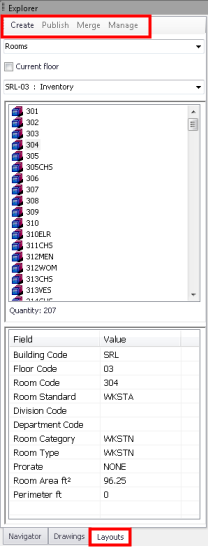
The commands for working with layout scenarios in CAD -- Create, Publish, Merge, and Manage -- are available on the Layouts tab of the Explorer pane.
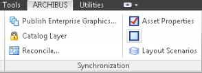
By default, the Layouts tab is hidden. To activate it, select the Layout Scenarios command from the Synchronization ribbon. From the command line, type afm_layouts.
Note: The Layout tab is available upon startup of AutoCAD 2016 and later. The layout functionality is not yet supported in the Archibus Smart Client Extension for Revit.