Archibus SaaS / Space / Move Scenarios
Space / Moves / Move Scenarios
CAD User: Create Layout Scenarios
Note: This topic assumes an understanding of Archibus asset types, asset layers, prototype layers, asset text layers, and asset tables. See Asset Symbols: Overview if you need to review these concepts.
To get started with layout scenarios, you must first create them using the Create command on the Layouts tab of the Explorer pane. Once you create a new layout scenario, it will be available for choosing in the Explorer pane's Layout tab.
To create a layout scenario:
- In the Smart Client Extension for AutoCAD load the inventory drawing from which you want to create a new layout scenario.
- Click the Create button the Layouts tab of the Explorer pane to run the Create command. (Activate the Layouts tab from the Layout Scenarios command on the Synchronization ribbon.)
- Complete the Layout Configuration form, as described below.
- Click the Create button at the bottom of the Layout Configuration form. The Create command generates a new layout scenario by doing the following:
- creates a new drawing for the layout scenario, if specified
- in the layout scenario drawing, creates any new layers specified in the Layout Configuration form; for example, RM-NORTHWING, RM-NORTHWING$, and RM-NORTHWING-TXT
- in the layout scenario drawing, copies the contents of the Inventory asset layer to the trial layer (the layer that you selected in the Layout Configuration form). For example, copies the content of the RM$ layer to RM-NORTHWING$. The room attributes copied are division, department, room category, room type, room standard, employee capacity, and area.
- in the layout scenario drawing, catalogs the contents of the trial layer. For example, catalogs the content of the RM-NORTHWING$ layer, thereby creating records in the RM-TRIALS table.
- adds the new layout scenario to the Select Layout list. This new layout will be the selected item in the Select Layout list.
Layout Configuration Form
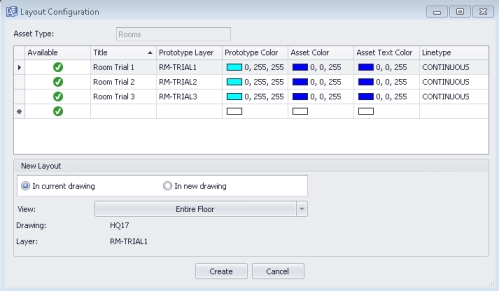
The Create command presents the Layout Configuration form for specifying the properties of the new layout scenario for the current drawing. The options are detailed below.
Asset Type
This options specifies the asset type on which the Layout Scenario will be based. The default value is Rooms, but you can also create equipment layouts.
Layers List
Use this part of the form to indicate the trial layer that you want to use for this layout scenario.
The form presents a list of the trial layer definitions for the Asset Type specified above; these definitions are stored in the Archibus Layers (afm_layers) table. Note that the Available column indicates whether or not the layer is already in use for the current drawing.
Click on a row to select the trial layer that the layout scenario will use. Once you choose a trial layer, the Layer option at the bottom of the Layout Configuration form displays your selection. For example, in the above image of the Layout Configuration form, the RM-TRIAL1 layer is selected (its row is highlighted in blue) and the Layer option at the bottom of the form displays this.

Defining and Editing Layers
For the Room asset type, the Archibus schema provides three pre-defined trial layers: RM-TRIAL1, RM-TRIAL2, and RM-TRIAL3. If you wish to change the colors of these layers, click on the color boxes to access a menu of optional colors. Likewise, you can edit the titles or layer names. This is handy for conveniently modifying the values from the form, instead of having to use Smart Client to access the Archibus Layers (afm_layrs) table and changing the prototype, asset layer, and asset text layer values for each trial layer.
If you need additional layers, you can create them by completing the bottom row of the form. For example, suppose you are creating a new layout specifically for the Facilities department. You could name the prototype layer RM-FACILITIES. This new layer is associated with the Room Trial asset type, so the asset symbols you create on this new layer will be recorded in the Room Trials table just as the assets created on the RM-TRIAL layers.
When creating a new layer, you must minimally complete the Title and Prototype Layer values.
| Field | Value | Example |
|---|---|---|
| Title |
Enter text that describes the content. This must be a unique value. |
North Wing Rooms |
| Prototype Layer |
This is an upper case value, and must be prefixed by the asset type, such as: RM-. |
RM-NORTH |
Once the form lists the desired layer with the desired properties, click on this layer to select it as the layer for the layout scenario.
View (Entire Floor or Partial Floor)
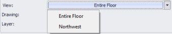
Use this option to specify that the layout scenario will use the full drawing or an AutoCAD view that you have developed. For example, if you are working with only one portion of the overall floor plan, you can develop an AutoCAD view of this area and then select this view for the layout scenario. See Creating Partial Layouts later in this topic.
Any views that you have developed for this drawing will be available for you to select by clicking on the View option.
Current Drawing or New Drawing
You can create the layout scenario in the current drawing, or in a new drawing.
One reason to create the layout scenario in a new drawing is if you know that you will be experimenting with the physical elements represented on the floor plan: the walls, doors, and windows. When you merge a new drawing with an inventory drawing, the Merge command applies the changes you make to walls, doors, and windows to the inventory drawing. For example, merging copies the Wall layer of the layout scenario drawing to the Wall layer of the inventory drawing. If on the layout scenario you deleted walls to combine two rooms into a larger room, this change will be copied to the Wall layer of the inventory drawing.
The Drawing option at the bottom of the Layout Configuration form displays the name of the layout scenario drawing you chose or the drawing that will be created.
- If the current drawing is specified, the name of the current drawing is displayed, such as HQ18.
- If a new drawing is specified, the name of the drawing that will be created is displayed. The name is based on the source drawing name, plus the prototype layer name, plus the view name (for partial layouts, discussed below).
- Existing drawings do not change names to reflect a partial layouts.
| Type of drawing | Syntax | Example Drawing Name |
|---|---|---|
| New drawing, entire floor | InventoryDrawingName-ProtoypeLayerName | HQ18-RM-TRIAL1.dwg |
| New drawing, partial floor | InventoryDrawingName-ProtoypeLayerName-ViewName | HQ18-RM-TRIAL1-NORTH.dwg |
| Existing drawing, partial floor | InventoryDrawingName | HQ18.dwg |
| Existing drawing, entire floor | InventoryDrawingName | HQ18.dwg |
Note: The DWG name does not change for an existing drawing for which you specify a trial layer. However, when you publish the inventory drawing with the trial layer active, the publish command generates an SVG file with the trial layer name appended to the drawing name. See Publishing: Naming SVG Files.
Note: If you exit AutoCAD without saving the current drawing, you will lose the layout scenarios created for this drawing during this session.
Creating Partial Layouts
Suppose you know that you will be working on only a portion of the overall floor plan; for example, you are reconfiguring the South Wing and the rest of the floor will remain as is. In this case, you can create a layout of only this part of the floor. This is known as a partial layout -- a subset of the entire floor plan.
A prerequisite for generating partial layouts is that you must create one or more Named Views in the AutoCAD drawings that partial layouts will be generated from. An AutoCAD Named View is a preset rectangular view of an AutoCAD drawing.
Define a Named View in AutoCAD
- Start the Smart Client Extension for AutoCAD and open the drawing for which you want to make a partial layout. For this example, open HQ17.
- Zoom into the section of the drawing that will be used for a partial layout, such as zooming into the upper left of the drawing, which will be used as the South layout.
- Make sure that your zoom fully includes all rooms that you want to be in the partial layout.
- If a room is not completely in the zoomed area, it will not be included in the partial layout and will not be available for editing in the layout scenario. .
- On the AutoCAD Ribbon, click the View tab, and then Named View.
- On the resulting Viewports form, click on the New Viewports tab.
- In the View Name, type in a name that indicates the planned layout, such as South Wing.
- Click OK on the Viewports form and save the drawing.
Creating a Partial Layout in the Current Drawing
This procedure continues with HQ17 as an example. Assume that you have made a named view for HQ17 using the above procedure.
- Click on the Layouts tab in the Explorer pane. (If the Layouts tab is not visible, click on the Layouts button from the Archibus ribbon to enable it.)
- On the Layouts tab, choose "HQ-17 : Inventory" as the current drawing.
- Click the Create button at the top of the Layouts tab.
- In the Layout Configuration form, create a row for the South Wing renovation.
- Select the South Wing row in the form.
- Choose Existing Drawing.
- Under the View option, choose South Wing. This is the named view that you created above.
Note: If you are creating a layout scenario in a new drawing that has a partial view, in the form's Drawing option, the Create command lists the name of the new layout scenario drawing, such as HQ21-RMTRIAL-South Wing.
Next
Once a layout scenario is created, you can work with the layout scenario to experiment with different configurations and assignments of space.