Space / Space Planning / Space Planner / Space & Portfolio Planning Console / Stack Plan Tab
Real Property / Advanced Forecasting / Advanced Portfolio Forecasting / Space & Portfolio Planning Console / Stack Plan Tab
Marking Up Images and Floor Plans
Note: This topic describes the redline and mark-up features that are included in views that use the HTML drawing control (the standard drawing control beginning with Archibus V.23.2). Custom views that use the Flash drawing control offer a similar, but different, set of redlining features. For information on Flash-based redlines, see Adding Redlines to Drawings (Flash drawing control).
Space planners and project managers may want to mark up floor plans and images to show proposed changes, notations, and highlights and then share these mark-ups with others in the organization. Markups are associated with action items, which are part of a project's work packages. When working with the Space & Portfolio Planning Console, you can add markups to your plans and images. If your portfolio scenario is linked to a project, you can select the project's action items to which to add markups. If the portfolio scenario is not linked to a project, you can create an action item and corresponding project directly from the markup forms.
Markups are also handy if you intend to generate move order to implement a proposed change. The markup can include redlines with notes of how to change the space. When the move scenario planner opens the generated move order, the move order will include these markups and the move scenario planner and CAD user can work from these markups to reconfigure the space and experiment with different layouts. See Proposed Moves report for information on generating the move order; see Moves: Move Scenario Planner for information on working with move scenarios.
Markups can include:
- redlines
- room highlights according to a pre-defined plan type, such as vacant rooms
- room highlights according to a filter you specify or a set of rooms that you select
- highlight legends
The below image of a map includes a legend, redlines, and text boxes. Highlights are available only for floor plans and not images. In this case, the user captured an image of a map and added the highlights using another program; they then added the redmarks and legends using Web Central's mark-up tools. For floor plans, you can highlight rooms directly in Web Central using the mark-up tools.

This topic contains the following sections:
- Prerequisite: Prepare the Floor Plan Drawing
- Step 1: Load the Floor Plan or Image
- Step 2: Add Redlines
- Step 3: Add Highlights
- Step 4: Save and Capture Markups
For additional examples of using the markup tools, see Example 6: Share Data from the Jansen Integration Scenario with Others.
Prerequisite: Prepare the Floor Plan Drawing
To work with this feature, you must have published your CAD plan as enterprise graphics in SVG format.
The system display the drawing with the layers that you have published. This is often a room plan drawing. However, if you are working with areas derived from a suite inventory (rather than a space inventory) and have published the Suites layer, then the system will display the suites so that you can mark up the suite plan. See the Space & Portfolio Planning Console and Areas.
Load the Floor Plan or Image if the Scenario is Connected to a Project or Move Project
Follow this procedure if the portfolio scenario is linked to a project,
- In the Space & Portfolio Planning Console's Stack Plan pane, choose the Mark Up button.
- If the scenario is connected to a project or move project, the system presents the Action Items form listing the project's action items. Use the filter at the top of the form to narrow the list if necessary. Or, if you wish to create a new action, choose the Add Action button and specify a name for the action item, and optionally the building and floor to which it pertains.
- For the desired action item, choose the Create Markup button. (If the action item already has a markup, the form will display the Edit Markup button so that you can make changes to an existing markup.)
-
The next step depends on if the action item references a floor that has a floor plan drawing published as enterprise graphics in SVG format.
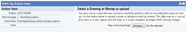
- If the action item does not reference a floor that has a floor plan drawing in SVG format, the system prompts you to select a bitmap, such as a scan of a floor plan or an image. For example, you may want to capture a GIS or Google Earth map or scan a site plan so that you can add markups to it. Note that once you select your image, the system activates the Upload Image button. Use this button if you decide that you want to abandon the current image and choose another.
- If the action item references a floor that has a floor plan drawing in SVG format, the system automatically loads the floor plan drawing and presents the markup tools in the left pane.

- If the action item does not reference a floor that has a floor plan drawing in SVG format, the system prompts you to select a bitmap, such as a scan of a floor plan or an image. For example, you may want to capture a GIS or Google Earth map or scan a site plan so that you can add markups to it. Note that once you select your image, the system activates the Upload Image button. Use this button if you decide that you want to abandon the current image and choose another.
- You can now use the mark up tools to add markups to the image or floor plan drawing, and then save the markup as described below.
Note: To use the mark-up features on CAD drawings, the CAD drawing be published in SVG format. For information, see Publishing Drawings as Enterprise Graphics.
Load a Floor Plan or Image if the Scenario is Not Connected to a Project
Markups are connected to a project's action items. However, if your scenario is not connected to a project, you can create a project and action item from the Mark Up feature. A license for the Projects application is not required.
- In the Space & Portfolio Planning Console's Stack Plan pane, choose the Mark Up button.
- The system presents an empty Action Items form. The Select Action Items section does not display any records.
- On the empty Action Items form, choose the Add Action button (indicated in below image) to access the Add Action Item form.
- Complete this form with a title and optionally the building and floor to which the action pertains. The system creates a project with the same name as the portfolio scenario and assigns this action item to it.

- You can now follow the above procedure, depending on whether or not your new action item references a floor that has an SVG drawing.
Add Redlines
You can add redlines to drawings and images to point out specific areas. For example, you may want to circle a room on a floor plan drawing that needs to be reconfigured as part of a space reorganization.
The Redlines panel offers several tools for marking up your floor plans and images.

Drag and drop the redline controls from the palette to the desired area of the drawing.
You can use the text tool and the swatch tool to create a legend of your highlight colors.
If you wish to use a color other than the default red, you can select Black or choose a custom color from the Custom button, on the right. If you set a custom color, the panel will display the Custom button in this color. All future redlines will use this color until you change the color again or exit.
Add Highlights
If you are working with a floor plan drawing, the left-hand panel includes the options for highlighting floor plan drawings. A few methods are available:
- plan type highlights (pre-defined)
- highlights for a restriction that you define
- highlights for an ad-hoc restriction (a set of rooms that you select)
Highlights are not available for images.
Once you add a highlight to the drawing, you can use the redlining swatch and text tools to create a legend explaining your highlight colors.
If you define multiple highlights, the system applies them to the floor plan in the order in which they were created. If a room is subject to multiple highlights, the system applies the highlight that was last added to the list of highlights. For example, you might want to set a plan type highlight to show vacancy and then select a few additional rooms that you know will become vacant in the near future.
Pre-defined plan type highlights
If you want to highlight the floor plan by department, room category, room standard, occupancy, or vacancy, use the pre-defined plan type highlights.

Choose a plan type highlight from the list, and the system highlights the drawing according to the defined plan type. If you wish to change the properties of a plan type highlight, use the Space Inventory / Background Data / Edit Standard Space Plan Types task.
Restriction Highlights
Instead of or in addition to the defined plan type highlights, you can highlight rooms by a filter restriction. The Filter Highlights list, located beneath the Plan Types list, lists the highlights you have defined and provides options for creating new highlights.

For example, you may need to highlight all rooms of a particular standard that are larger than a particular size because these rooms are not adhering to the standard definition and need to be examined.
- If desired, set a plan type highlight to which you will add an additional restriction highlight. Or, set the plan type highlight to None.
- Under Filter Highlights, click Filter Rooms. The system presents the Filter Rooms form for defining the restriction. For example, the below image calls for highlighting all conference rooms assigned to the Facilities-Design department so that you convert these rooms to storage.

- Complete the Filter Rooms form to define the restriction and click Add Filter. The system highlights the drawing and adds the restriction title and highlight color to the "Filter Highlights" list. If you need to further edit the restriction or delete it, use the buttons in the Filter Highlights list.
Ad Hoc (Select Room) Highlights
Instead of or in addition to the defined plan type highlights, you can highlight rooms by selecting them. You may have a situation in which you want to select a series of rooms that have no common criteria. In this case, you can create the restriction by clicking on the rooms.
- If desired, set a plan type highlight to which you will add the ad hoc highlight. Or, set the plan type highlight to None.
- Under Filter Highlights, click Select Rooms. The system moves you to the drawing frame.
- At the top of the frame, enter a descriptive title of the highlight restriction and select the color for this highlight restriction. For example, in the below image, the user has assigned a title of "Merge these rooms."

- Select the rooms you want to highlight.
- Click Add Filter in the top right area of the form, and the system saves this restriction. In "Filter Highlights" on the left, it displays the color and the title that you specified in Step 3. If you need to further edit the restriction or delete it, use the buttons in the Filter Highlights list.
Save or Capture Markups
There are a few ways to save your markups for access by others.
- If you generate a Powerpoint of the portfolio scenario, the resulting PowerPoint file will include the markups for the scenario's action items.
- The Capture Image button saves the SVG drawing or image with its markups as a PNG file. The system opens a new browser tab with the markup image, which you can then print or download to a desired location.
-
When you click Save, the system creates a screen-scrape and saves it to the Document 4 document field of the Action Items table (the
activity_logtable). The system saves to the Archibus Redlines table (afm_redlines) the data that is necessary to re-create the markup and highlighting so you can edit it later on. The screen-scrape itself does not have enough information for you to later edit. - If the portfolio scenario is linked to a project or move project, you can examine the mark-up in the project or move project. See Moves: Move Scenario Planner,
Note: Archibus Redlines table. The system creates a record in the Archibus Redlines table (afm_redlines) as soon as it opens (unless you're editing an existing record). This happens even before you click Save. It does this because it needs a record to exist in afm_redlines before saving a document in the corresponding activity_log record. This is counter-intuitive, and is a known issue.
Note: Exporting and Importing Markup in Projects -- If you are exporting and importing markup into and out of a project, be aware of the following: in order to access the markup when you import it back into the project, both the activity_log record and the afm_redline record must be exported. If only the activity_log record is exported , when the record is imported back in, the Edit Markup button will not show; the view will show only a button for Create Mark Up, which does not access your existing document.