Archibus Foundations / Space and Moves / Space Console
Options for Printing Drawings from the Space Console
When printing from the Space Console using the various Export commands available from the Export icon, you can set the appearance for the printed output.
You control the highlights and labels by using the Highlights and Labels buttons, or, alternately, by selecting a plan type. Highlights, labels, and plan types are available out-of-the box with Archibus, and they might provide the appearance you want the printed output to have. However, you can also make ad hoc adjustments to change the appearance.
Note the use of PNG and EMF formats:
- Exports the full extents of drawing's highlights, layers in original EMF file in high-res format (EMF) for:
- Export Floor Plans in Floors List to PDF
- Export Floor Plans in Floors List to WORD
- Generate Ad Hoc PDF Report when
- Choose “Yes” to “Print just the current drawing?” option AND do not change the zoom level of the drawing.
- Choose “No” to “Print just the current drawing?” option
- Export drawings with highlights, layers shown on screen and zoom level in low-res format (PNG) for:
- Export What you See to DOCX
- Generate Ad Hoc PDF Report when users choose “Yes” to “Print just the current drawing?” option AND change the zoom level of the drawing.
Ad Hoc Adjustments (current print session only)
The following are some of the ad hoc adjustments you can make that affect only the current print session.
- Defining text size (Label Height): Text size is determined by the label height. This is defined in the plan type or the PDF view AXVW file used for printing. If you do not want to use the predefined label heights, you can change this using the Print Options dialog. See Setting Print Options.
- Selecting background layers to include in the printed output. You can select background layers, as a separate drop-down option on the drawing control. Based on publishing rules, the system publishes multiple enterprise graphics files for desired background layer combinations (rooms, equipment, emergency egress, etc.). The “background layers” drop-down lists the layer combinations available, and then the on-screen and printed floors display the corresponding layers selected. See Printing Background layers.
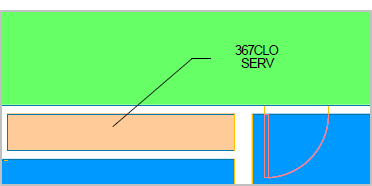
- Leader lines: By way of an AutoCAD command, the CAD Specialist can “turn on” leader lines to publish. Leader lines can exist on the asset text layer or the A-LEDR layer. When published, they are included in the background material. Combined with text position (below), showing leader lines enables cases where information about small rooms must be placed outside of the rooms themselves. The following image shows a floor plan drawing that uses leader lines with the text position outside the room:
- Zooming to an area of the drawing You can print a zoomed-in section of a drawing by setting this in the Print Options dialog. When you select this option, the system prints only the drawing shown in the drawing control. See Setting Print Options later in this topic.
- Use a consistent scale for the printed set. You can set this option to print drawings to a consistent scale. This give a visual comparison of area size across drawings. When this option is selected, the printing process chooses the smallest standard scale factor for the set and applies it to all floors in the set. See Consistent Scale later in this topic.
- Legend Shading Color. This option enables you to change the shading color of the printed legend. The value for the legend color is set as a 6-digit Hex Color. The default is 0xDBE5F1, but you can enter a different color value in this field,. To turn off legend shading, set the color to white, which is ‘0xFFFFFF’”.
- Legend hatch block size: The size you select is applied to the hatch block, as long as the highlighted pattern is a hatch pattern. The default size for this field is “Medium”. You can change the size by selecting “Large”, “Small”, or keeping it “Medium”.
Note: The legend hatch size applies only if the highlight pattern is a hatch pattern. If the highlight patterns are solid colors, the color fills the entire cell, and its size cannot be changed.
Note: If the highlight block size shows bigger than desired, you can modify the PDF template to increase the width of the legend area. This will increase the width of each row, thus making text fit into one row that would otherwise have to wrap to two rows. The legend is a text block in the template, so to change its overall width, you just change the width of the text block (and reduce the width of the text block for the drawing).
- Max Label Lines: Specifies the maximum number of text label lines that any asset (room) prints. For example, if there are multiple employees in the same room, this would restrict the number of employees (text label lines) to show. A default value of “0” means “show all”.
- Legend fields. The printed output uses the legend datasource defined in the active_plantypes record, or the print legend datasource that is associated with the highlight you select. A legend configuration is associated with the selected Plan Type and will display on the printed output. So, you can change the legend fields by selecting different plan types or highlights.
The Business Process Owner can edit plan types or add new plan types as needed. See Edit and Create Plan Types.
The Add-In Manager for your deployment can add templates or plan types for additional highlights, legends, and report labels, so that you have the standard selections you need for viewing and printing drawings. Contact your Add-In Manager if you require additional standard choices. See Options for printing drawings to PDF and Doc format (System Management Help).
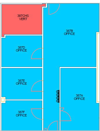
The application brings over the CAD-specified position on the published JSON file, and uses this position by default. If the JSON file does not have this information (for example, when you have upgraded and the JSON file has not yet been re-published), then the system reverts to the method of the weighted center, that is, it uses a system-generated position that is centered in a room for printed output. To change the position of the text in the printed output and on-screen, have your CAD specialist change the position in the CAD drawing. This changes the default text position used when printing.
The following image shows the PDF output for a drawing with asset text positioned in CAD for an L-shaped room.
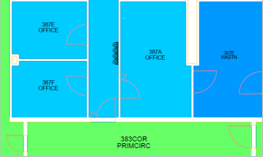
The following image shows a report where the text height for the primary circulation, office, and the workstation varies, because it’s taken from the text height specified in CAD.
After selecting a highlight or a plan type, you can make ad hoc adjustments to the drawing . These changes are for your current print session only. Following is the overall process for setting the appearance for the drawings you print from the Space Console:
- Determine which drawings are exported. Determine the drawings you want to print by setting a filter in the Locations list. When printing to PDF, the drawings showing in the Locations list are what is exported. Alternately, you can select the check boxes for one or more drawings to display them on the right, and then export what's seen to a DOCX file.
Tip: If you select the check box for at least one drawing, that drawing appears in the drawing pane, so that you can see how the selections you make affect the highlights and labels. Printing what you see can be useful in certain situations, for example, if you want to print multiple floors on the same sheet of paper.
- Set how the drawings appear. Do one of the following to specify how the exported files appear.
- Highlight and labels. Select these from the lists at the top of the console.
For details on selecting highlights, see:
- Plan type. Select a plan type by selecting the gear icon, and then selecting Plan Type from the menu. A pop-up window appears from which you select the plan type. See Selecting a plan type.
- Highlight and labels. Select these from the lists at the top of the console.
- Select a background layer. Select a background layer if one has been published that includes background elements that you want included in the printed output. Out-of-the-box, the application includes published background layers for leader lines, emergency egress, and equipment. For example, you can print the drawing showing leader lines if you have published a background layer for this. See Selecting and printing background layers.
- Set print options. If you are exporting to PDF, you can set print options, such as whether or not to use a consistent scale, label height, color for legend shading, and whether you want to print the zoomed-in drawing. If you set printing options, this must be your final step, as the print options are not saved after you exit the dialog. When setting print options, you export the drawings to PDF clicking the Export button and selecting the Generate Ad Hoc PDF Report option. See Setting printing options.
- Select an export method. If you are not setting print options, export the drawings using one of the following export menu options:
- Generate PDF of floors in Locations List
- Generate DOCX of floors in Locations List.
- Export what you see to DOCX.
If you want to print using standard settings, you can select a Highlight and Label from the lists at the top of the Space Console and not make any further adjustments.
However, after selecting a highlight and labels, you can set print options (when exporting to PDF), or you can select a background layer to be included in the export. (when exporting to either PDF or DOCX.) See Selecting a plan type and Selecting a background layer.
When you select a Highlight and Label, you cannot select a plan type.
If you select a highlight and label from the lists, by default, the system gets the following to print the drawing:
- Legend. The legend datasource is derived from the print legend datasource that is currently associated with the selected highlight option.
- Label Height. This is defined in the print AXVW file, not the database. You can, however, override the label height by setting print options when exporting to PDF.
If a drawing is displayed in the right pane, after you select the Highlight and Legend, the drawing pane displays the drawing using the selections you make, so you can see how the printed output will appear. You can show a drawing in the right pane by selecting its check box in the Locations list on the left.
For details on selecting highlights, see:
- Highlight Rooms in your Floor Plan by One Property
- Highlight Rooms in your Floor Plan by Two Properties
Plan types are different views of your drawing that use specific highlight, labels, and legends. For example, at different times, you might want to have a view of your floor plan which highlights rooms by occupancy, and at other times, a view which highlights rooms by room category. You can select a plan type to use the highlight, labels, and legends defined for that plan type when printing the drawing. The plan type is defined in the associated active_plantypes record. Your Add-In-Manager defines the plan types that you need. Your Business Process Owner can edit plan types as needed. See Edit and Create Plan Types.
See the following topic in the System Management Help:
Plan types are another option for standard printing, but after selecting a plan type, you are also able to set print options (when exporting to PDF) or select a background layer to include the elements in that layer in the export (when exporting to either DOCX or PDF.)
When you select a plan type from the drop-down list, the Space Console gets the highlight, label, and legend datasources from the associated Active Plan Types (active_plantypes) record. The Space Console shows these highlights and labels on the drawing, and uses them to export to PDF, using the legend datasource for the legend.
If you select a plan type, you cannot choose a Highlight, Border, or Label from those lists on the Space Console, as these are handled by the plan type. If you select a plan type, then the Highlight and Label drop-downs show “None.” Conversely, if you choose a Highlight or Label in the drop-down lists, the Plan Types list shows “None."
The plan types available on the Space Console have the "Standard Space Highlights" Plan Type Group. Only plan types that have this Plan Type, and that are set as active are shown on the Space Console.
What the plan type determines
Plan types determine the following:
- Labels and Highlights. The drawing control and the printed output use the datasources for the labels and highlights defined in the plan type.
- Legend fields. The printed output uses the legend datasource defined in the active_plantypes record to produce the legend fields that the printed output uses
- Label Height: This is the label height for PDF output in points (1 point = 1.333 pixels.) This determines the text size.
- Max Label Lines: Specifies the maximum number of text label lines that any asset (room) prints. For example, if there are multiple employees in the same room, this would restrict the number of employees (text label lines) to show. A default value of “0” means “show all”.
Procedure: Selecting a plan type
To select a Plan Type:
- Determine the floors to be printed by using the Filter console to show the drawings in the Location list.
- To see one of the drawings in the drawing control, select its check box. When you make this selection, the drawing will show the formatting for your selections.
- Click the gear icon from the top of the console to display the menu for printing:.
- Select Plan Types from the menu.
The Select Plan Types dialog appears.
The Plan Type list includes the Plan Types that ship with the application.
- From the Plan Type list, select the Plan Type you want to use for printing.
The plan type includes label, legend, and highlight datasource information, label height, and max label lines as defined above.
- Click Save.
If you have selected the check box for a drawing in the Locations list, the drawing pane shows the drawing using the plan type you selected.
Next steps:
- If no adjustments are needed, print the drawings using one of the export actions. Select the export icon and then select one of the following:
- Generate PDF of Floors in the Locations List
- Generate DOCX of Floors in the Locations List.
- Generate DOCX of what you see - this exports only the drawing shown in the drawing control.
Note: For DOCX export, you are not able to set printing options as you are for PDF output.
- Select a background layer, such as one including leader lines, to be included in the printed output. See Setting and printing background layers.
- If you are exporting to PDF, you can select print options. To do so, select the export icon and then select Generate Ad Hoc PDF Report. Set print options as needed , and select Export to run a job that creates the PDF. This options exports all drawings shown in the Locations list. See Setting Print Options.
- If no adjustments are needed, print the drawings using one of the export actions. Select the export icon and then select one of the following:
If you want to add an altogether new plan type, add it to the Active Plan Types table (active_plantypes), which you can access from the Smart Client's Views tab. From the Active Plan Types table, you can also set multiple labels and highlight data sources -- for instance you can have one set of highlighting and labels for vacant rooms and another set for occupied rooms.
To make the new plan type appear on the Space Console, use the Smart Client's Views tab to load the Plan Type Groups table (plantype_groups), assign your new plan type to the "Standard Space Highlights" group, and make sure the Active? value is set.
Often, you want your floor plans to show underlying background detail -- such as architectural plan lines, the equipment or furniture plan, the emergency plan, or other groups of layers. You can choose the layers to show by selecting background layers.
When the CAD Manager publishes enterprise graphics, the system publishes the drawings using all active drawing publishing rules. Based on publishing rules, the system can publish multiple SVG files (for viewing the drawing online) and EMF files (for printing the drawings) for multiple background options (rooms, equipment, emergency egress, lines, etc.), each with a different suffix.
Note: When working with EMF, you must make sure that the suffix associated with the EMF publishing is the same as the suffix associated with the background layers for SVG publishing. In addition, note that:
1. Even though you must select more than one background layer to view on the drawing control, the command prints only the last selected layer.
2. Because background layers available in the SVG file are both those "registered" in afm_dwgpub and those visible when publishing, it's possible the selected background layer will not print if it's in the latter category and not the former.
The application includes drawing publishing rules for the following out-of-the-box:
- Architectural plan lines
- Equipment
- Emergency egress
Note: For the steps to publish leader lines, see Publishing Drawings with Leader Lines.
Once your follow the steps to publish leader lines, the leader lines background layer appears in the list.
After your CAD specialist runs the Publish Enterprise Graphics action from the Archibus Extension for AutoCAD, then these published background layers are available for your selection.
If there is more than one publishing rule that publishes out to EMF, you can select which background (EMF file) to show, and subsequently print, from the Space Console. For example, you might have one option that prints with the leader lines; and another option that prints without.
Your CAD and BIM manager can define drawing publishing rules for other background layers that you want to see and print in your drawings. See the topic Editing Drawing Publishing Rules.
Tip: When publishing a background layer for leader lines, the leader lines must be on the same layer as the asset text.
Procedure: Selecting a background layer
To select a background layer:
- From the Space Console, select a drawing and either a highlight and label or a plan type to determine how the drawing is displayed. See Selecting a Plan Type or Selecting a Highlight and Legend for Exporting Drawings.
- Click the gear icon from the top of the console to display the menu for printing:
- Select Background from the menu.
The Select Background Layer dialog appears. The Background Layer list shows the layers that have been published for that floor using your drawing publishing rules. The background layers available out-of-the-box include: equipment, leader lines, and emergency egress
- Select a background layer from the list.
The drawing view switches to show the corresponding SVG file. When printing, the system prints the corresponding EMF file with the same selected background layers.
Next steps
- If no further adjustments are needed, print the drawings using one of the export actions. Select the export icon and then select either:
- Generate PDF of Floors in the Locations List
- Generate DOCX of Floors in the Locations List.
- Generate DOCX of what you see - this exports only the drawing shown in the drawing control.
- If you are exporting to PDF, you can select print options. To do so, select the gear icon and then select Print Options. Set print options as needed , and select Export to run a job that creates the PDF. This options exports all drawings shown in the Locations list. See Setting Print Options.
- If no further adjustments are needed, print the drawings using one of the export actions. Select the export icon and then select either:
You create a background layer group by creating a new Drawing Publishing rule. You can do so in the Smart Client with the System / CAD and BIM Manager / Edit Drawing Publishing Rules task. Once the rule is in place, the Publish Enterprise Graphics command will publish your background layer group along with the other graphic information.
Set the following for the drawing publishing rule.
- Layers. In the Additional Layers property, specify the layers of the drawing that should be in the background layer group.
- Colors. Use the Color Mapping property if you want the layers to print in a different color than they appear in CAD or BIM. For instance, you might want all architectural plan lines to appear in a background gray color rather than red, yellow and the other colors used to draw them.
- Type. Use a SVG type rule to have your backgrounds appear in the Space Console; use a "SVG and EMF" rule to have your background appear in the Space Console and in PDF and DOCX reports. Any rule of these two types will appear in the Select Background Layers dialog. .
- Suffix. Use a Rule Suffix. The Publish Enterprise Graphics command publishes a separate enterprise graphics file for each drawing and rule. The rule suffix makes the name of this layer group file unique from all other background layer groups.
See Publishing Drawings as Enterprise Graphics and Controlling How Enterprise Graphics are Published.
You can make ad hoc changes in the drawings exported to PDF by selecting the Generate Ad Hoc PDF Report option from the Export icon.
- For all print options except printing the zoomed-in drawing, the system prints the floors shown in the Locations list, not the floors shown in the drawing control in the right pane.
- If you select to print the zoomed-in drawing, the system prints only the drawing that is currently displayed
To set printing options for the current print session:
- Determine the drawings to be exported. See Determining the floors that are exported.
- Select either a plan type or a highlight / labels for printing. See Selecting a plan type or Selecting a highlight, labels, and legend for exporting drawings
- If needed, select a background layer. See Selecting and printing background layers.
- From the Space Console, click the export icon from the top of the console to display the print options, and select Generate Ad Hoc PDF Report.
-
The PDF Print Options dialog opens.
- Set the following options as needed:
-
Print the just the current drawing. The default is set to No so that the printed output shows floors to their full extents. To print the floor as it is zoomed in on the drawing control, set this to Yes. If you print a zoomed image, note that the system prints only the floor portion currently displayed, and the legend shows metrics for the full floor.
Note the following about the generated file:
- When you choose “Yes” to this option, and you change the zoom level of the drawing, the system generates a PNG file.
- When you choose “Yes” to this option, and you do not change the zoom level of the drawing, the system exports the full extents of the drawing's highlights and layers in the original EMF file in high-res format .
- When you choose “No” to this option, the system exports the full extents of the drawing's highlights and layers in the original EMF file in high-res format .
- Use consistent scale for the printed set:
- Set this option to Yes if you want the printing process to scale all floors equally, thus giving a visual comparison of area size across drawings. When the Yes option is selected, the printing process chooses the smallest standard scale factor for the set and applies it to all floors in the set.
Note: When using consistent scale, the system must use a “standard” scale. For example, 1/8 or 1/3. For this reason, even the biggest floor may not take up the whole area designated for the printed drawing.
- If you leave the selection as the default, 'No', each floor is scaled to meet the provided printed area – the program finds the largest standard scale that will fit on a given output paper size, and then scales by that amount (and displays the scale in the title block.)
- Set this option to Yes if you want the printing process to scale all floors equally, thus giving a visual comparison of area size across drawings. When the Yes option is selected, the printing process chooses the smallest standard scale factor for the set and applies it to all floors in the set.
- Label height:
- This is the default label height for PDF output in points (1 point = 1.333 pixels). This parameter determines text size.
- If you selected a Plan Type, then the system populates the label Height parameter with the value from
active_plantypes.label_ht.pdf. If you did not select a Plan Type, then the value defaults to “3”, which is the value in the labelHeight tag inab-sp-console-export-drawing-pdf.axvw. In either case, you can enter a different value to override these defaults for this printing session.
-
Legend Shading Color. This option enables you to change the shading color of the printed legend. The value for the legend color is set as a 6-digit Hex Color. The default is 0xDBE5F1, but you can enter a different color value in this field,. To turn off legend shading, set the color to white, which is ‘0xFFFFFF’”.
- Click Export.
This action exports the drawings shown in the Locations list to a PDF file.The Paginated Report View appears. When the generation is complete, the link to view the PDF is activated.
Back to
-
Space Console Overview