Archibus Smart Client: System / CAD and BIM Manager
Archibus Web Central: System / CAD and BIM Manager
Configure Application Parameters for CAD and BIM Publishing to SVG
In order to ensure floor plan and legend consistency throughout the organization, Archibus provides a set of global drawing publishing parameters that define how your models and drawings will be published to SVG enterprise graphics. These application parameters set publishing properties, such as floor plan opacity, globally for all floor plans and all users.
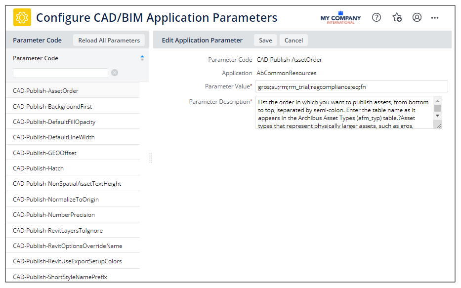
Access the parameters from the System / CAD and BIM Manager / Configure Application Parameters for CAD and BIM task (ab-cad-def-activity-parameters.axvw), which groups together all publishing configuration options in one view. The task is available from both Web Central and Smart Client.
The parameters apply to all floor plans throughout the organization, and override settings made by each user using the Publish Enterprise Graphics command's Preferences form (Archibus Smart Client Extensions for CAD and Revit).
For users familiar with setting the publishing preferences from the Smart Client Extensions for AutoCAD and Revit, the below tables outlining the parameters include the corresponding option set with the Publish Enterprise Graphics command's Preferences form (Archibus Smart Client Extensions for CAD and Revit).
Publishing Order Parameters
When the drawing publishing routine generates the SVG file, it is important that the items be visible and accessible (you can click on them to work with them). Typically, you will want to have large items (such as gross areas) on the bottom and smaller areas (such as rooms) on the top so that you can see these items and select them. For example, if the publishing routine draws the rooms on top of equipment, and the rooms are filled, the user is not able to click on the equipment or drag-and-drop equipment items.
Archibus ships with a standard order, but you can fine-tune the order by working with the below parameters.
| Application Parameter | Description | Corresponding Location on Smart Client Publish Enterprise Graphics Command |
|---|---|---|
|
CAD-Publish-BackgroundFirst |
Publish drawing background? This includes anything that is not an asset symbol and is not defined in the Archibus Asset Types table. 1= Yes. 0=No. Default value is 1 (Yes). |
Visibility and Accessibility / Background |
|
CAD-Publish-SpatialFirst |
Publish spatial (boundary-type) assets (such as Gross and Rooms). 1= Yes. 0=No. Default value is 1 (Yes). |
Visibility and Accessibility / Spatial |
|
CAD-Publish-AssetOrder |
List the order in which you want to publish assets, from bottom to top, separated by semi-colon. Enter the table name as it appears in the Archibus Asset Types (afm_typ) table. Asset types that represent physically larger assets, such as ‘gros’, should be in the beginning of the list. The default value is: gros;su;rm;rm_trial;regcompliance;eq;fn |
Visibility and Accessibility / (The form displays a tree) |
|
CAD-Publish-UnspecifiedAssetTypesFirst |
Unspecified asset types that you want to be more visible than asset types specified in the AssetOrder list (above). 1= Yes. 0=No. Default value is 1 (Yes). |
Visibility and Accessibility / Unspecified asset types display order |
Optimization Parameters
When drawing publishing converts AutoCAD layer names to SVG style names and AutoCAD block names to SVG symbol names, the resulting file names can become very large. This can produce very large SVG documents, which can be hard to work with. Large SVG files are produced when drawings are exported from Revit or if they include external references. For example, an AutoCAD block could be named as follows in the generated SVG file: 0649-01$0$University Chemistry_Level_2 FURN$0$Manager Chair_1_1. By instructing the program to use short symbol names with a prefix such as SYM, this name could be reduced to SYM01.
Use these parameters to produce smaller symbol and style names, and thereby produce a smaller SVG file.
| Application Parameter | Description | Corresponding Location on Smart Client Publish Enterprise Graphics Command |
|---|---|---|
|
CAD-Publish-UseShortSymbolNames |
Do you want to use short symbol names instead of normal symbol names? 1= Yes. 0=No. Default value is 0 (No). |
Optimization / Use Short Symbol Names |
|
CAD-Publish-ShortSymbolNamePrefix |
If you set the above option to Yes, specify a prefix for short symbol names. Default value is SYM. |
Optimization / Symbol Name Prefix |
|
CAD-Publish-UseShortStyleNames |
Do you want to use short style names should instead of normal style names? 1= Yes. 0=No. Default value is 0 (No). |
Optimization / Use Short Style Names |
|
CAD-Publish-ShortStyleNamePrefix |
If you set the above option to Yes, specify a prefix for short style names. Default value is LYR |
Optimization / Style Name Prefix |
|
CAD-Publish-NumberPrecision |
Enter the precision of all numbers in the SVG file. The default value is 2, which is a precision of 0.01 inches. Metric users may want to increase this value to 3. Symbol definitions will have a precision of the set precision, plus 1. This is to ensure that symbol definitions which typically require a higher precision than the rest of the SVG contents are more correctly rendered. |
Optimization / Precision |
|
CAD-Publish-NormalizeToOrigin |
Normalize to Origin? For drawings that are offset from the 0,0 by large distances, such as > 1,000,000 ft, activating this parameter ensures that the generated enterprise graphics files display correctly in Web Central. 1= Yes. 0=No. Default value is 0 (No). |
Optimization / Normalize to Origin |
Look and Feel Parameters
| Application Parameter | Description | Corresponding Location on Smart Client Publish Enterprise Graphics Command |
|---|---|---|
|
CAD-Publish-DefaultFillOpacity |
Enter a number between 0 and 1 (ex. 0.7) to specify the opacity of solid hatch areas within the Enter t 1 to make colors in drawings exactly match the colors in legend swatches drawn elsewhere in Web Central. Default value is 0.7 |
Look and Feel / Fill Opacity |
|
CAD-Publish-DefaultLineWidth |
Enter the line width (in inches or centimeters) for the finest line width in the SVG. Record the unit of measurement after the number that represents the width. For example: 2.1-cm or 2.1-inch. Default value is 2.0-inch. |
Look and Feel / Line Width |
|
CAD-Publish-SpatialAssetTextHeight |
Specify the font size in ‘em’ units for spatial assets text. Please enter a number with one decimal (ex. 1.5). Default value is 1.0. |
Look and Feel / Height of Spatial Asset Labels |
|
CAD-Publish-NonSpatialAssetTextHeight |
Specify the font size in ‘em’ units for non-spatial assets text. Please enter a number with one decimal (ex. 0.5). Default value is 0.4 |
Look and Feel / Height of non-Spatial Asset Labels |
|
CAD-Publish-RevitOptionsOverrideName |
The name of a predefined export setup in the Revit model to be applied at publish time. If not specified, the default export setup will be used. The default value is ARCHIBUS. |
Look and Feel / Use predefined Revit export setup |
|
CAD-Publish-RevitUseExportSetupColors |
Use the Revit Category colors. If not, will use the colors in the temporary DXF file. 1= Yes. 0=No. Default value is 0 (No). |
Look and Feel / Use Revit Category Colors |
Content Parameters
| Application Parameter | Description | Corresponding Location on Smart Client Publish Enterprise Graphics Command |
|---|---|---|
|
CAD-Publish-Hatch |
Determines whether the command publishes any AutoCAD hatches, solid or non-solid. Solid hatches are the most efficient, as they are a single setting on a boundary, while line-based fills translate to many SVG elements and result in larger SVG file sizes. Does not affect output from Revit. 1= Yes. 0=No. Default value is 0 (No). |
Contents / Publish Hatches |
|
CAD-Publish-GEOOffset |
Determines whether the publishing process applies a geospatial offset when creating SVG files to georeference the output. This typically is not used for SVG drawings used in the Web Central HTML drawing control or the mobile drawing display. In those environments, the drawing is shown within its own extents and not in a map or georeferenced context. 1= Yes. 0=No. Default value is 0 (No). |
Contents / Apply Geospatial Offset |
|
CAD-Publish-RevitLayersToIgnore |
List the name of the layers to ignore, separated by semi-colon. You can specify relative names by using an asterisk. Default value is G-ANNO-* |
Contents / Layers to ignore |