Archibus Web Central
Adding Redlines to Drawings (Flash drawing control)
Note: Beginning with Archibus V23.2, all Web Central views were converted to use the HTML drawing control. If you have a custom view that uses the Flash drawing control, follow the instructions in this topic to work with the redlining features. Views that use the HTML drawing control operate slightly differently. For information on redlining using the HTML Drawing Control, see Marking Up Images and Floor Plans.
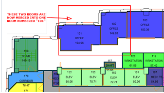
Non-CAD users can add redlines to drawings to indicate location areas directly on a floor plan drawing. Once you add redlines, the system saves them as a document. Other users can access the redlines using the system's document management features. For example, a user might access a document to review an image of the floor plan with redlines such as the following:

Use redlines to perform tasks such as:
- Indicate a location when submitting a service request
- Indicate a specific location within a room or other area on the floor plan where an employee safety incident occurred.
- Position equipment (such as fire extinguishers) or furniture in a room, with the goal of having this equipment added to the .dwg drawing.
- Request a furniture or employee move in an open plan office by drawing arrows on a floor plan to indicate the intended location.
- Review changes made to a floor plan.
Many types of users benefit from adding redlines to drawings. For example:
- Department managers can provide feedback to CAD specialists on field conditions, such as, new walls, or rooms that have been joined.
- CAD managers can review a CAD specialist's drawing changes.
- Maintenance managers, service desk managers, safety managers, and so on can graphically see the exact location of an issue.
- Architects might need to review all the changes that have been made to a drawing. The redlines can serve as a record of the requested changes. For example, when an architect is updating the as-built drawings for a portion of a building prior to a renovation, it can be helpful to review all redlines made to that portion of the building in all service requests.
Adding Redlines
When working in applications such as Health & Safety, Service Desk, or Corrective Maintenance, you can add redlines to the floor plan drawing to indicate the location of an item. For example, if you have done a complete survey of the floor, you might find that the as-built drawing is no longer correct, you can create a service request and make redlines on the floor plan drawing to indicate the changes that need to be made.
Tasks for which you may want to add drawing redlines launch drawing frames that include the redline tools on the right edge of the drawing frame.

Note the following:
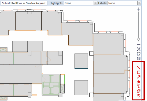
- On the right edge, the drawing control displays icons for tools to work with redlines:
- Draw Line
- Draw Rectangle
- Draw Arrow
- Draw Position Marker (star icon)-- Places a small red dot (position marker) where you click on the drawing.
- Draw Text
- Clear Redlines
- Undo the last redline.
- Click an icon to activate it, and then click and drag on the drawing to use this tool.
- To add text, click the Draw Text (T) icon, and click and drag to create a text box on the drawing. When you release the mouse, a cursor appears in the left corner of the text box you created. Type within the text box to add the desired text.
Before adding the redlines, you may wish to focus on an area by zooming and panning. Or, you may wish to display room numbers or other highlights. For information, see Working with Drawings.
Saving Redlines
When you save redlines, the program saves the view of the drawing currently on the screen - including highlights, labels, and redlines - as a .png image file. If you select Save when you have zoomed in, and not all redlines are visible, a pop-up window appears asking if you want to keep the current view or zoom out until all redlines are visible, and then save the image file.
The image file containing the redlines is uploaded to the appropriate document field of the parent item (such as a service request or incident report) as a file attachment. Users can view the redlines by choosing it from a task that presents the document field.
The system saves the redlines as vectors in the in the Archibus Redlines table along with all data needed to regenerate the redlined floor plan.