Drawing Boundaries Accurately
There are several commands that will both speed drawing and improve accuracy. While there are many tips and tricks to working in CAD, this topic overviews the key skills you will find useful if you are drawing interior gross areas and room boundaries.
Standards for Drawing Accuracy
When you draw new room boundaries or place doors, a 6-inch or 10-cm accuracy suffices for most facilities. That is, you can draw to a snap grid that is 6"x6" or 10cmx10cm and produce a plan detailed enough for space management and planning.
The only exception would be results that are audited. This is the case for spaces that are to be used for indirect-cost recovery. Hospitals that charge space back to insurance carriers or universities that charge space back to government grants find themselves in this situation. In this case, consult the administrator of your chargeback program as to the desired level of accuracy. Typically this is within 1 inch or 2.5 cm.
Organizations that charge back space to leases do not need this higher level of accuracy, as the chargeback is based on the negotiated area of the lease, which does not match the actual areas derived from CAD or BIM.
Drawing to IFMA, BOMA, FICM or IPD Standards
In some cases, you will want to draw your drawings to an industry standard, such as IFMA, BOMA, or IPD depending on your industry and country. Some organizations adopt these standards for consistency.
While they differ in detail, as regards drawing, the essential difference in these standards is how they define the boundaries of interior rooms.
- Some standards define interior space as extending to the interior face of the wall. In this case, drawing using snap modes is often helpful, as you can use the endpoint snap to snap exactly to the endpoints and intersections of the existing wall lines.
- Other standards define interior space as extending to the center of interior walls, to the face of structural elements like columns, and to the dominant interior edge of walls containing windows. In this case, it is often useful to user your snap modes for drawing the edges of exterior walls and structural elements and the snap grid for the centerline of interior walls.
- If you are drawing to a particular standard, do be aware that the standards categorize interior space differently. For examples of how to configure Archibus for different standards, see Mapping IFMA and BOMA Conventions to an Archibus Space Inventory.
- One final note on standards is this: unless you are defining data that must meet the strictures of a particular regulation -- such as chargeback for healthcare facilities or university research spaces using Federal grant money -- the particular standard you use is fairly arbitrary from the standpoint of overall space planning and management, as long as you are consistent. If you have your choice of standard, you may wish to choose:
- Drawing rooms to the center line of walls and the face of structural elements if you are working from BIM models (as Revit will define areas in this matter automatically)
- Drawing rooms to the face of walls if you are working with AutoCAD (as the BPOLY command described below can create this type of outline automatically).
Units Command
When you use thew New Drawing command from an Archibus menu, the Archibus New Drawing dialog ensures that you properly register the drawing as metric or Imperial. However, you may with to use the Units command to set the scale in which the AutoCAD status line and commands display units information.
For Imperial drawings:
- Choose Type of Architectural
- Choose Precision of 0 (making 1" the smallest unit of distance shown)
In Imperial drawings, one AutoCAD "unit" of distance is 1" for all drawings. For metric drawings, one AutoCAD "unit" of distance (that is, what AutoCAD chooses to consider a whole number) changes between M, cm, and mm based on country.
For Metric Drawings:
- Choose Type of Decimal
- Choose a precision that makes sense for your base units, typically 2 for Metric units and 0 for cm and mm units.
Tip: Additional setting for Units are available by selecting the Space Inventory / Room Inventory - Set Up and Manage / Units task. By selecting this task, you access the AutoCAD command to set units and see the full range of options. A Help button in the Units dialog provides a description of the available options.
Ortho Mode

Most lines within a plan are rectilinear. As such, you may wish to constrain your point selection to purely horizontal or purely vertical lines. To do so:
- use the "Toggle Ortho Mode" selection from the Navigator, which turns ortho mode on or off
- alternately, click the AutoCAD bottom status line button that looks like a right angle
- alternately, type ORTHO at the AutoCAD command prompt
The Snap Grid

For facility management or lifecycle management drawings, you typically need a 6" or 10 cm accuracy. In some less common cases, in which your areas are used for cost chargeback calculations that are subject to audit, you will need a 1" or 2 cm accuracy.
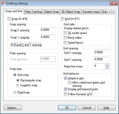
You can speed your drafting by setting a snap grid to this smallest required accuracy. The snap grid makes certain that each line or polyline you draw begins or ends on this grid. For instance, if you set a 6"x 6" snap grid, all points you draw will "snap" to that grid. This setting makes it easy to begin and end lines -- such as the polylines for adjacent rooms -- from exactly the same point.
Object Snap Modes

In some cases, you will want to start the next point -- such as the beginning corner of an adjacent room -- from an existing point, such as the corner of the last room you drew. In this case, use the Object Snap command again, but set the Object Snap tab as pictured.
This dialog lets you turn on and off "snap modes" that will make your cursor snap to points on existing elements.
BPOLY Command

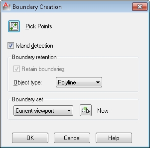
If you are drawing rooms to the face of walls, you can save a great deal of time by using the "BPOLY" command. This command can draw the boundary of an enclosed room in one step.
To use the command:
- Use the "LAYER" command to turn on any lines that enclose your rooms, such as window lines, wall lines, or door lines
- Use the Set Rooms command from the Archibus Navigator menu to set to the room layer
- Invoke it by typing "BPOLY" at the AutoCAD command prompt
- Select the "Pick Points" option, then select a point within each enclosed room. Press enter when done.
The command will create a separate, enclosed polyline for each room.