Archibus Web Central
Working with Floor Plans
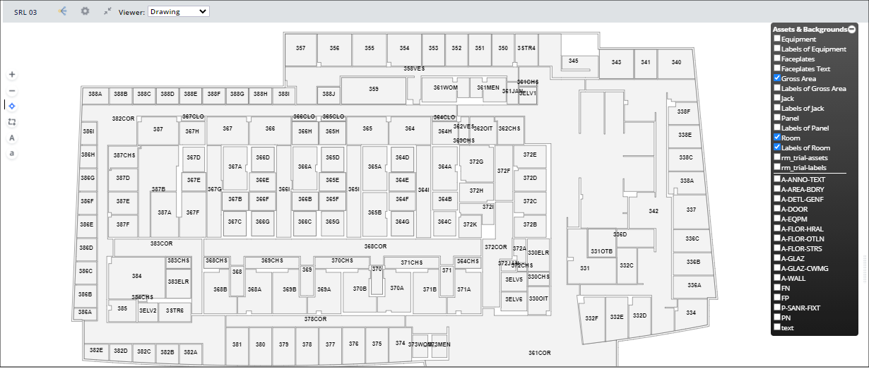
Archibus views use the HTML drawing control to display enterprise graphics of your floor plans or site plans within Web Central views.
Note: Prior to Archibus V.23.2, many Web Central views used the Flash drawing control and newer views used the HTML drawing control. Beginning with Archibus V.23.2, all Web Central views use the HTML drawing control, described in this topic. If you have a custom view that uses the Flash drawing control, see Working with Drawings (Flash).
SVG Format
The HTML drawing control requires SVG files. Therefore, you must publish your floor plan drawings as enterprise graphics in SVG format using:
- the Publish Enterprise Graphics command from Smart Client Extension for AutoCAD
- the Publish 2D command in Revit
Zooming
There are a several ways to adjust the zoom setting:
- Use the mouse wheel for wide-scale zooming.
- Turn the wheel up to zoom in.
- Turn down to zoom out.
- Click the mouse.
- Double-click while on the drawing to zoom in at 1.25 the current scale.
- Use the zoom commands on the drawing control toolbar, which is located on the left side of the drawing window (see above image for its position, and below image for the icons).
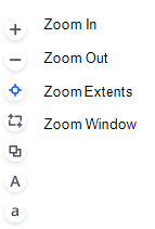
Controlling the Label Size
Drawings can display labels, such as the room number, equipment code, or employees located in a room. From the side toolbar, use the "A" icon to increase the label size, and the "a" icon to decrease the label size. These icons are shown in the above image of the toolbar.
Panning
To pan:
- Use the mouse click-move-release action to pan the drawing, except when you are in "Zoom into Selected Window Area" or "Select Multiple Assets" mode.
- Use the Up, Down, Left, Right arrow keys.
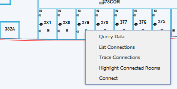
Right-click Menu
Some views offer a right-click menu that presents additional commands. For example, when using the Telecom Console view, you can right click on a telecom asset symbol to receive a list of commands for connecting the symbol. Right-clicking on a room presents a menu with a different set of commands.
Selecting Assets
As you work with floor plans, you will need to select rooms, equipment assets, telecom assets, and so on. To do so, click on the items. If you accidentally select an asset, you can remove it from the selection set by clicking on it.
Depending on the type of asset, the drawing highlights it or outlines its border in gray (rooms).
To select multiple assets at once with a “click-drag-release” event
The drawing provides a tool for making a selection set of several assets with a “click-drag-release” event:
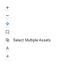
- Click the "Select Multiple Assets" icon on the toolbar.
- Select the desired assets by clicking, dragging over the desired items, and then releasing.
- The drawing highlights or outlines in gray each item that is at least partially located within the selection box.
- If you accidentally select an asset, you can remove it from the selection set by clicking on it.
- Similarly, if you want to add to the selection set that was not originally in your selection box, click on it.
- When your selection set is completed, press the Esc key.
Setting Layers
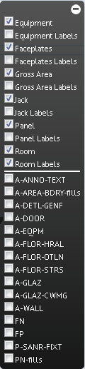
Each view displays the floor plan with a default set of layers visible. Use the toolbar in the right corner (pictured below) to display additional layers, such as labeling text, wall boundaries, or doors, if these items were published as part to the SVG enterprise graphics file. Click a layer's check box to toggle the layer between displaying and hiding. Turning on too many additional labels may make your drawing too crowded and hard to work with.
You can hide the label menu by clicking its expand and contract button, located in its upper right corner.
Redlining and Markup
See Marking Up Images and Floor Plans.
Highlighting Drawings by One or Two Properties
While some views automatically highlight the drawing by a various property (such as the Highlight Rooms by Standard), other views enable you to choose the information by which to highlight the drawing. Such views include a Highlights command and also present a legend so that you know the value that each highlight color represents. The Highlights option lists the various properties by which you may want to highlight your drawing; for example, you could highlight an item by department ownership, standard, category, and so on. Simply choose the property from the Highlight option's drop-down list.
Sometimes you may need to see multiple properties at one time on a drawing. In these cases, the view may offer a secondary highlight, known as a border highlight, which highlights the drawing according to a secondary property.
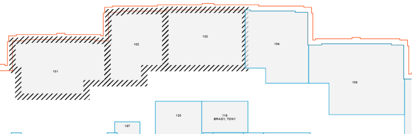
For example, the below image shows a floor plan highlighted by room standard and occupancy. Each room is solid-filled with a color associated with the room standard, and a second color (the border highlight) outlines the boundary of each room in a color indicating its occupancy. The user has invoked the Legend command to display a legend to explain the various highlight and border highlight colors. The Highlights, ]Border Highlights, and Legend commands are indicated by the red box.
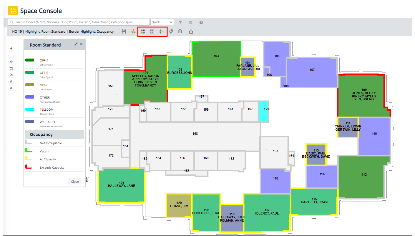
Note: Highlight colors are associated with their corresponding record. For example, the Room Standards table includes a Highlight Pattern ACAD field with which you can set the highlight color to use for solid fills or border highlights of rooms according to room standard. The above image shows room 101, an OFF-A room standard, as highlighted in green; accordingly, the record in the Room Standards table that defines the OFF-A room standard has green as the value for its Highlight Pattern ACAD field. See Define Highlight Patterns.
Other highlights, such as pending space requests, are defined as part of the view. To change these highlight colors, a system administrator must edit the view file.