Smart Client Extension for Revit
Smart Client Extension for AutoCAD
Controlling How Enterprise Graphics are Published (Preferences form)
When you publish your CAD drawings as Archibus enterprise graphics, the drawing publishing rules control what layers are output to enterprise graphics and the format of the graphic (SVG, JSON, etc) that is generated. In addition, the various graphic types offer options for fine-tuning how the enterprise graphics are generated.
To specify these options, you work with the Preferences form.
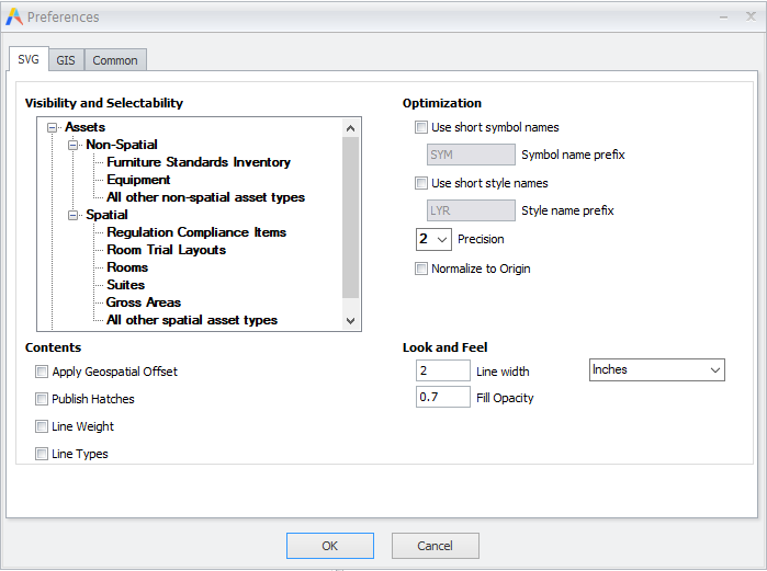
Access the Preferences form from:
| Program | Command | Option |
|---|---|---|
| Smart Client ExtensionRevit | Publish 2D | On the resulting Publish Enterprise Graphics form, choose the Options button. |
| Smart Client Extension for AutoCAD | Publish Enterprise Graphics | On the resulting Publish Enterprise Graphics form, choose the Options button. |
Note: For details on publishing Revit 3D plans for use in the 3D Navigator, see Publish 3D.
Typically, a site will determine the way that they want to publish the enterprise graphics and use these settings for all drawing publishing. However, it is possible to change settings for individual executions of drawing publishing. For example, if for a particular drawing you want to change the accessibility and visibility of certain assets for SVG output, you can run the Preferences command to make the change and then publish the drawings. You can then return the options to their original settings when you are through. The dialog will save your most recent settings between invocations.
This topic has sections to cover each tab on the Preferences form:
- SVG tab (for use with mobile and Web Central views that use the HTML drawing control)
- GIS tab: JSON and KML (for use with enhanced map views)
- Common tab: logging options
SVG options
SVG is used for drawings that will be accessed by:
- mobile devices and accessed
- Web Central views that use the HTML drawing control.
Note: Beginning with V.2022.02, the options listed in the SVG tab of the Preferences form are also specified as application parameters, which are set using the System / CAD and BIM Manager / Configure Application Parameters for CAD and BIM task. To ensure consistency throughout the organization, the parameters apply to all drawings that you publish to SVG enterprise graphics. The application parameters override settings made with the Preferences form's SVG tab. Use the Preferences form's SVG tab for one-time exceptions, when you need to have different settings for just one session.
Note: Beginning with Archibus V.23.2, Web Central views were converted from using the Flash Drawing Control and SWF format to using the HTML drawing control and SVG format. You may have custom views that use the Flash Drawing Control and SWF format.
Determining visibility and accessibility of items in the SVG output
When the drawing publishing routine generates the SVG file, it is important that the items be accessible (you can click on it to work with it) and visible. Typically, you will want to have large items (such as gross areas) on the bottom and smaller areas (such as rooms) on the top so that you can see these items and select them. For example, if the publishing routine draws the rooms on top of equipment, and the rooms are filled, the user is not able to click on the equipment or drag-and-drop equipment items.
Archibus ships with a standard order, but you can fine-tune the order by working with the Visibility and Accessibility option. The items in the form are listed in decreasing order of their visibility and selectability. For example, in the below image furniture is the most visible (at the top of the list) and Gross Area is the least visible (at the bottom of the list).
- Drag and drop items within the list to change the order of visibility and selectability. For example, if Equipment items should be most visible and selectable, drag "Non-Spatial" to the top of the list and within the "Non-Spatial" list, drag Equipment to be the first item.
- To remove an item from the list, right click on it and choose Delete from the menu.
- Add other asset types to the list by moving to either Spatial or Non-Spatial, right-clicking, choosing Add, and choosing an asset type from the Archibus Asset Types table.
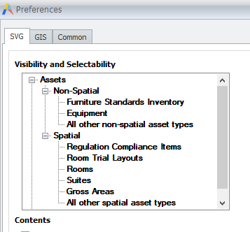
The below table defines the elements of the Visibility and Accessibility option. For each option, the below table lists the corresponding application parameter, which is set with the System / CAD and BIM Manager / Configure Application Parameters for CAD and BIM task.
| Option | Includes | Corresponding Application Parameter |
|---|---|---|
| Background |
Anything that is not an asset symbol and is not defined in the Archibus Asset Types table. |
CAD-Publish-BackgroundFirst |
| Spatial | Boundary-type assets (such as Gross and Rooms) | CAD-Publish-SpatialFirst |
| All Other Spatial Asset Types |
Spatial asset types that are not explicitly listed in the form. To see what this list includes, right-click and choose Add; the program lists all of the boundary-type assets defined in the Archibus Asset Types table that you have not yet specified. You can position this item at the top or the bottom of the Spatial list, but not in the middle. |
CAD-Publish-AssetOrder |
| Non-Spatial | Non-boundary types of assets (Equipment and Furniture). | CAD-Publish-UnspecifiedAssetTypesFirst |
| All Other Non-Spatial Asset Types |
Non-spatial asset types that are not explicitly listed in the form. To see what this list includes, right-click in Non-Spatial and choose Add; the program lists all of the block-type assets defined in the Archibus Asset Types table that you have not yet specified. You can position this item at the top or the bottom of the Non-Spatial list, but not in the middle. |
CAD-Publish-UnspecifiedAssetTypesFirst |
In addition to the above explicit control over organization, in order to support the concept of rooms in rooms, the command orders assets of the same asset type in their own grouping as follows:
- Boundary asset types by their area value, largest to smallest.
- Non-boundary asset types by their maximum Z value, smallest to largest.
Optimization: Reducing the size of the SVG file
When drawing publishing converts AutoCAD layer names to SVG style names and AutoCAD block names to SVG symbol names, the resulting file names can become very large, and can produce very large SVG documents, which can be hard to work with. This happens when drawings are exported from Revit or if they include external references. For example, an AutoCAD block could be named as follows in the generated SVG file: 0649-01$0$University Chemistry_Level_2 FURN$0$Manager Chair_1_1. By instructing the program to use short symbol names with a prefix such as SYM, this name could be reduced to SYM01.
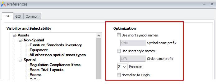
Use these options to reduce SVG file size. For each option, the below table lists the corresponding application parameter, which is set with the System / CAD and BIM Manager / Configure Application Parameters for CAD and BIM task.
| Option | Description | Corresponding Application Parameter |
|---|---|---|
| Use Short Symbol Names | Determines whether short symbol names should replace the normal symbol names. If you choose this option, you can specify a prefix for symbol names. | CAD-Publish-UseShortSymbolNames |
| Symbol Name Prefix | If you set the above option, use this option to specify the prefix. |
CAD-Publish-ShortSymbolNamePrefix |
| Use Short Style Names | Determines whether short style names should replace the normal style names. If you choose this option, you can specify a prefix for symbol names. | CAD-Publish-UseShortStyleNames |
| Style Name Prefix | If you set the above option, use this option to specify the prefix. | CAD-Publish-ShortStyleNamePrefix |
| Precision |
Enter the precision of all numbers that are included in the SVG file. The default value is 2, which translates to a precision of 0.01 inches. Metric users using meters as their unit of length may want to increase this value to 3. Note: symbol definitions will have a precision of the set precision + 1. This is to ensure that symbol definitions which typically require a higher precision than the rest of the SVG contents are more correctly rendered. |
CAD-Publish-NumberPrecision |
| Normalize to Origin | For drawings that are offset from the 0,0 by large distances, such as > 1,000,000 ft, checking this option ensures that the generated enterprise graphics files display correctly in Web Central. | CAD-Publish-NormalizeToOrigin |
Contents options
| Option | Description | Corresponding Application Parameter |
|---|---|---|
| Apply Geospatial Offset | Determines whether the publishing process applies a geospatial offset when creating SVG files to georeference the output. This typically is not used for SVG drawings used in the Web Central HTML drawing control or the mobile drawing display. In those environments, the drawing is shown within its own extents and not in a map or georeferenced context. | CAD-Publish-GEOOffset |
| Publish Hatches | Determines whether the command publishes any AutoCAD hatches, solid or non-solid. Solid hatches are the most efficient, as they are a single setting on a boundary, while line-based fills translate to many SVG elements and result in larger SVG file sizes. Does not affect output from Revit. | CAD-Publish-Hatch |
| Line Types |
Do you want to reflect line types in the published graphics ? 1= Yes. 0=No. Default value is 0 (No). Publishing line weights and line types enables the floor plans that you access in Archibus to look the same and use the same standards as as dictated your CAD policies. Usage Note; Archibus does not publish Leader and Multi-Leader Lines. (AD-9507, DOC-2603) |
CAD-Publish-LineTypes |
| Line Weight |
Do you want to reflect line weights in the published graphics ? With this option set to Yes, if there are non-default line widths (weight) on AutoCAD entities, they will be used when publishing to SVG. Default value is 0 (No). Publishing line weights and line types enables the floor plans that you access in Archibus to look the same and use the same standards as dictated your CAD policies. |
CAD-Publish-LineWeight |
| Additional Option for Revit | ||
| Layers to ignore | List the name of the layers to ignore, separated by semi-colon. You can specify relative names by using an asterisk. Default value is G-ANNO-* | CAD-Publish-RevitLayersToIgnore |
Look and Feel options
| Option | Description | Corresponding Application Parameter |
|---|---|---|
| Line Width |
Enter the line width (in inches or centimeters) for the finest line width in the SVG. When multiple floor plans are displayed at the same time, the line width will be identical across all floor plans when viewing the same relative size of the floor plans. Set Inches or Centimeters in the drop down option. |
CAD-Publish-DefaultLineWidth |
| Fill Opacity | Determines the opacity of solid hatch areas within the SVG. Leave this at 1 to make colors in drawings exactly match the colors in legend swatches drawn elsewhere in Web Central. | CAD-Publish-DefaultFillOpacity |
| Additional Options for Revit | ||
| Use predefined Revit export setup | The name of a predefined export setup in the Revit model to be applied at publish time. If not specified, the default export setup will be used. | CAD-Publish-RevitOptionsOverrideName |
| Use Revit Category Colors | Use the Revit Category colors. If not, will use the colors in the temporary DXF file. 1= Yes. 0=No. Default value is 0 (No). | CAD-Publish-RevitUseExportSetupColors |
GIS tab: JSON and KML (for use with enhanced map views)
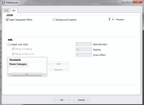
You may want to include enterprise graphics in enhanced map views. For example, you may wish to include the floor plan of a building with the GIS map showing the entire campus. Access these options from the GIS tab of the Preferences form.
JSON Options
| Apply Geospatial Offset | Whether or not a geospatial offset, if it exists in the Archibus Drawings (afm_dwgs) table, will be applied to the generated SVG JSON file. Please see the "Geospatial Offset and Projection" discussion below. |
| Background Graphics | Include the background graphics in the JSON output. Typically, you do not need to include the background graphics in a generated JSON file as the existing Esri process does not make use of that information. |
| Precision |
Enter the precision of all numbers that are included in the JSON file. The default value is 2, which translates to a precision of 0.01 inches. Metric users using meters as their unit of length may want to increase this value to 3. Note: symbol definitions will have a precision of the set precision + 1. This is to ensure that symbol definitions which typically require a higher precision than the rest of the JSON contents are more correctly rendered. |
| Workflow Rule Name |
The workflow rule to call. The name of the server side post process to be run. String: Default: “AbCommonResources-ArcgisExtensionsServiceForSmartClientExtension-publishFeaturesToArcgisServer” Will not georeference json files that have already been georeferenced . Will project from the local geographic coordinate system to Web mercator. Use the server-side projection library. |
Geospatial Offset and Projection
To properly offset (translate the coordinates of your elements to the proper latitude, longitude, and rotation) and transform (to convert the coordinates from their original state-plane coordinate system to Web Mercator coordinate system), use the Publish Enterprise Graphics geospatial options in the combinations below.
| If you are publishing from ... | to ... | Apply the Geospatial Offset? | Run the Post Publish Process? |
|---|---|---|---|
| AutoCAD drawings | Esri ArcGIS | No | Yes |
| Revit models | Esri ArcGIS | Yes | Yes |
| AutoCAD drawings or Revit models | KML | Yes | N/A |
If you are publishing AutoCAD drawings to Esri ArcGIS, you can depend on the post-publish process to apply the geospatial offset.
If you are publishing from Revit, you must have the Smart Client Extension for Revit apply the geospatial offset, as the geospatial properties come from the Revit model and are not available to Web Central, only to the Smart Client Extension.
Apply Geospatial Offset
In AutoCAD, when you insert and scale each floor plan on a base map to geolocate it, the "Save Georeference Information" task in the Archibus Smart Client Extension write the following location properties to the Archibus Drawings (afm_dwgs) table record for each floor plan. The properties are as below.
| Property | Description | Sample Value |
|---|---|---|
| Geo X Insertion (geo_x) | The longitude of the lower-left building corner on the base map. | 717525.10 |
| Geo Y Insertion (geo_y) | The latitude of the lower-left building corner on the georeferenced campus base map. | 3015644.90 |
| Geo Scale (geo_scale) | Records the scale used to scale the building plan when xreferencing it onto the campus base map. For Imperial unit in which floor plans are typically in Inches and base maps in feet, this scale factor is 1/12th. | 0.083333 |
|
Geo Rotation(geo_rotate) |
The rotation used when xreferencing the floor plan onto the campus base map. | 180.00000 |
| Geo Level (geo_level) | The nominal level of the floor. In ArcGIS or in the KML output, Archibus will show all floors of the same nominal level at the same vertical or z-coordinate. In this way, floors that are connected (even by small ramps or stairs) appear on the same level for space planning purposes | 11 |
| Geo Spatial Reference System | The coordinate system (e.g. the State Plane Coordinate System) used on georeferenced the campus base map. Most registries identify the same coordinate systems with the same numbers, but Archibus expects the number as per the EPSG Geodetic Parameter Registry. |
For Revit, these geoparameters come from the Revit model itself. You specify them when you use the Manage / Coordinates / Publish Coordinates tools to publish shared coordinates. Once you link a Revit model into a campus map or survey plan, that model then uses the shared coordinate system relative to the Project Base and Survey Points.
See Georeferencing and Publishing (System Management Help) for procedures on how to georeference your floor plans and models.
KML Options
Archibus provides KML publishing as an unsupported tool for those sites that wish to use Google Earth or other KML-compliant programs. Since GIS technology is changing rapidly, Archibus may change this feature or the underlying technology in future releases.
Archibus publishes the KML to the enterprise graphics folder of your project, such as projects\hq\enterprise-graphics.
The current feature is geared towards campus-scale space planning and publishes room and gross area boundaries.
| Publish with JSON |
If you want to generate KML output when you generate JSON output, check this option. For instance, if you publish the HQ17.DWG file highlighted by department and room category, Archibus will produce two files named:
If this option is checked, you can then also set the other options below options. |
| Merge to Building |
By default, the KML publishing publishes a single KML for each standard and floor. If you select the Merge to Building option, the KML publishing will also create a single KML for each building, and this KML will contain all floors in the KML. Typical files produced would be:
|
| Merge to Site |
If you select the Merge to Building option, the KML publishing will also create a single KML for each site, and this KML will contain all floors in the KML. Typical files produced would be:
|
| Base Elevation | Specifies the elevation of the lowest floor relative to the ground. The default value is 1. |
| Spacing | Specifies the spacing between floors, in feet. The default value is 15. |
| Gross Offset | Specifies the offset in the Z direction for the Gross boundary as compared to the elevation of the rooms contained in it. The reason for this offset is that it is possible that if the Gross boundary is drawn at exactly the same elevation as the rooms, that some of the room highlighting is obscured. This will ensure that the Gross boundary is drawn slightly below the room boundaries. Default value is -0.5 feet. |
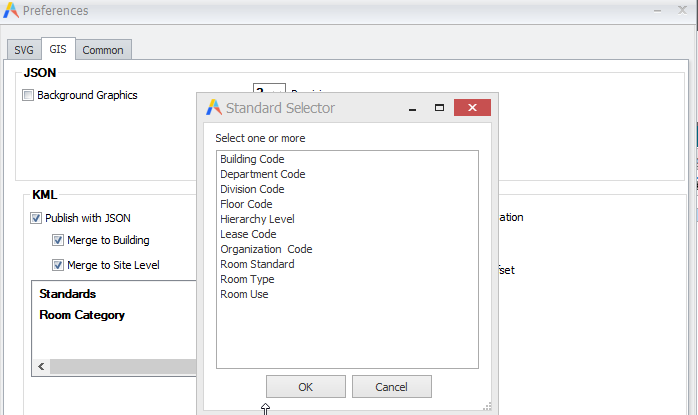
If you are publishing rooms, you can select a list of one or more standard categories by which the KML should thematically render the output. The KML publishing will produce one KML file per floor, building or site for each standard category you select. Choose the Add button in the KML section to access the Standard Selector form from which you can choose a standard category.
Common tab (logging)
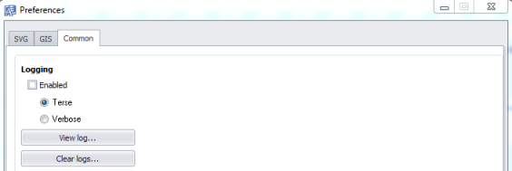
You may wish to enable the logging features so that you can identify and diagnose errors that may occur during a Publish Enterprise Graphics operation. Once you generate the log, you can review it using the View Log button.
You will want to enable logging only if you encounter an issue when publishing and need to track it.
